surendermehta
Member
- Joined
- 29 May 2011
- Messages
- 45
- Reaction score
- 27
Dear Friends,
As you know LNB is a low noise block-down converter receiving device used to collect signals of a satellite with dish antenna. It is functionally equivalent to the dipole antenna used for most terrestrial TV reception, although it is actually waveguide based. Inside the LNB waveguide a metal pin, or probe, protrudes into the waveguide at right angles to the axis and this acts as an aerial, collecting the signal travelling down the waveguide.It is usually fixed on the satellite dish framework, at the focus of the reflector, and it derives its power from the connected receiver.
.

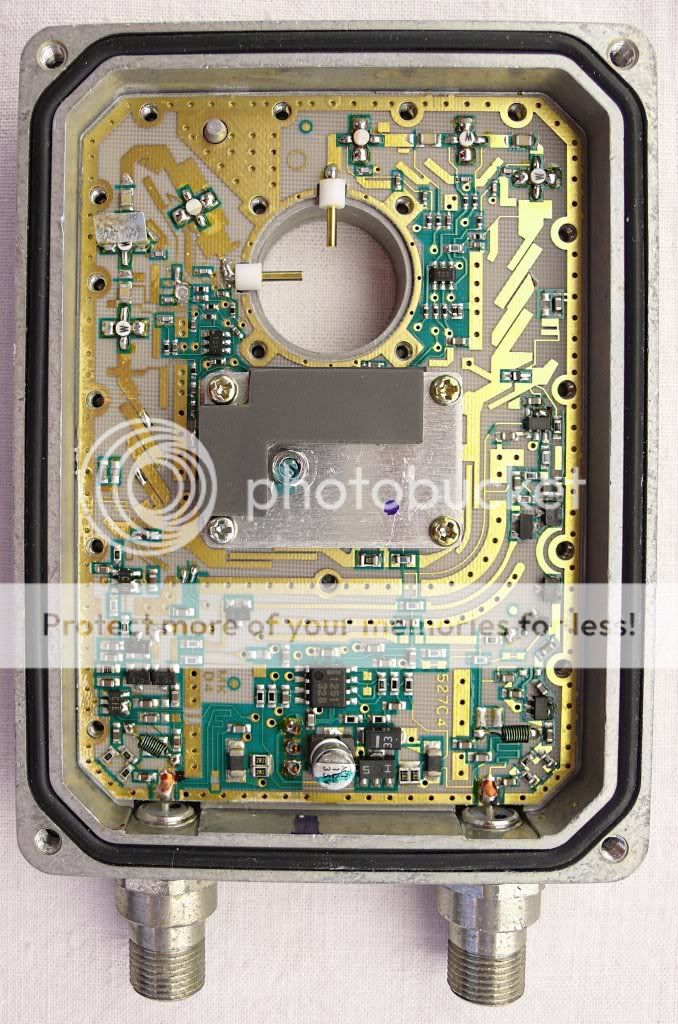
Disassembled C Band LNB
Satellites use microwaves to transmit their TV signals. As microwave satellite signals do not easily pass through walls, roofs, or even glass windows, satellite antennas are required to be outdoors, and the signal needs to be passed indoors via cables. When radio signals are sent through coaxial cables, the higher the frequency, the more losses occur in the cable per unit of length. The signals used for satellite are in the multiple gigahertz that special cable types or waveguides would be required and any significant length of cable leaves very little signal at the receiving end.
The purpose of the LNB is to use the superheterodyne principle to take a block (or band) of relatively high frequencies and convert them to similar signals carried at a much lower frequency (called the intermediate frequency or IF). These lower frequencies travel through cables with much less attenuation, so there is much more signal left at the satellite receiver end of the cable. It is also much easier and cheaper to design electronic circuits to operate at these lower frequencies, rather than the very high frequencies of satellite transmission.
The frequency conversion is performed by mixing a fixed frequency produced by a local oscillator inside the LNB with the incoming signal, to generate two signals equal to the sum of their frequencies and the difference. The frequency sum signal is filtered out and the frequency difference signal (the IF) is amplified and sent down the cable to the receiver:
IF frequency = received frequency - local oscillator frequency
The local oscillator frequency determines what block of incoming frequencies is downconverted to the frequencies expected by the receiver. For example, to downconvert the incoming signals from Insat 4B, which transmits in a frequency block of 10.70GHz-11.70GHz, to within a standard European receiver’s IF tuning range of 950MHz-2150MHz, a 9.75GHz local oscillator frequency is used, producing a block of signals in the band 950MHz-2150MHz.
LNBFs
With the launch of the first DTH broadcast satellite in Europe (Astra 1A) by SES Astra in 1988, antenna design was simplified for the anticipated mass-market. In particular, the feedhorn (which gathers the signal and directs it to the LNB) and the polarizer (which selects between differently polarized signals) were combined with the LNB itself into a single unit, called an LNB-feed or LNB-feedhorn (LNBF), or even an "Astra type" LNB. The prevalence of these combined units has meant that today the term LNB is commonly used to refer to all antenna units that provide the block-downconversion function, with or without a feedhorn. LNBs without a feedhorn built-in are usually provided with a (C120) flange around the input waveguide mouth which is bolted to a matching flange around the output of the feedhorn or polarizer unit.
Universal LNB

A Universal LNB has a switchable local oscillator frequency of 9.75/10.60GHz to provide two modes of operation – low band reception (10.70-11.70GHZ) and high band reception (11.70-12.75GHz). The local oscillator frequency is switched in response to a 22kHz signal superimposed on the supply voltage from the connected receiver. Along with the supply voltage level used to switch between polarizations, this enables a Universal LNB to receive both polarizations (Vertical and Horizontal) and the full range of frequencies in the satellite Ku band under the control of the receiver,
Svolt -Tone-- LOFreq--- Polarity ------ R Freq Band------- IF Range Used
13V 00KHz 09750MHz Vertical Low (10700-11700MHz) 0950-1950MHz
18V 00KHz 09750MHz Horizontal Low (10700-11700MHz) 0950-1950MHz
13V 22KHz 10600MHz Vertical High (11700-12750MHz) 1100-2150MHz
18V 22KHz 10600MHz Horizontal High (11700-12750MHz) 1100-2150MHz
Monoblock LNBs
A Monoblock LNB is a unit consisting of two LNBs and is designed to receive satellites spaced close together, generally 6°. For example Dish tv India is using monoblock to receive the NSS 6, 95°E and Asiasat 5 100.5°E satellites, enable reception of both satellites on a single dish without requiring an expensive, slow and noisy motorised dish.
Multi-Output LNB

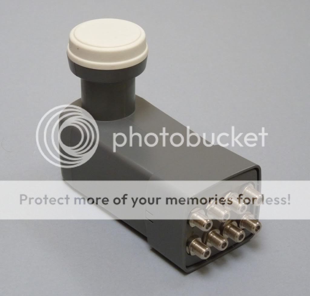
There are Dual/Twin/Quad/Octo output LNBs. We can connect and receive channels on multi stbs.
HD LNB
we read in many posts about HD LNB, there is no any difference between HD or SD LNB.
Wikipedia
As you know LNB is a low noise block-down converter receiving device used to collect signals of a satellite with dish antenna. It is functionally equivalent to the dipole antenna used for most terrestrial TV reception, although it is actually waveguide based. Inside the LNB waveguide a metal pin, or probe, protrudes into the waveguide at right angles to the axis and this acts as an aerial, collecting the signal travelling down the waveguide.It is usually fixed on the satellite dish framework, at the focus of the reflector, and it derives its power from the connected receiver.
.

Disassembled C Band LNB
Satellites use microwaves to transmit their TV signals. As microwave satellite signals do not easily pass through walls, roofs, or even glass windows, satellite antennas are required to be outdoors, and the signal needs to be passed indoors via cables. When radio signals are sent through coaxial cables, the higher the frequency, the more losses occur in the cable per unit of length. The signals used for satellite are in the multiple gigahertz that special cable types or waveguides would be required and any significant length of cable leaves very little signal at the receiving end.
The purpose of the LNB is to use the superheterodyne principle to take a block (or band) of relatively high frequencies and convert them to similar signals carried at a much lower frequency (called the intermediate frequency or IF). These lower frequencies travel through cables with much less attenuation, so there is much more signal left at the satellite receiver end of the cable. It is also much easier and cheaper to design electronic circuits to operate at these lower frequencies, rather than the very high frequencies of satellite transmission.
The frequency conversion is performed by mixing a fixed frequency produced by a local oscillator inside the LNB with the incoming signal, to generate two signals equal to the sum of their frequencies and the difference. The frequency sum signal is filtered out and the frequency difference signal (the IF) is amplified and sent down the cable to the receiver:
IF frequency = received frequency - local oscillator frequency
The local oscillator frequency determines what block of incoming frequencies is downconverted to the frequencies expected by the receiver. For example, to downconvert the incoming signals from Insat 4B, which transmits in a frequency block of 10.70GHz-11.70GHz, to within a standard European receiver’s IF tuning range of 950MHz-2150MHz, a 9.75GHz local oscillator frequency is used, producing a block of signals in the band 950MHz-2150MHz.
LNBFs
With the launch of the first DTH broadcast satellite in Europe (Astra 1A) by SES Astra in 1988, antenna design was simplified for the anticipated mass-market. In particular, the feedhorn (which gathers the signal and directs it to the LNB) and the polarizer (which selects between differently polarized signals) were combined with the LNB itself into a single unit, called an LNB-feed or LNB-feedhorn (LNBF), or even an "Astra type" LNB. The prevalence of these combined units has meant that today the term LNB is commonly used to refer to all antenna units that provide the block-downconversion function, with or without a feedhorn. LNBs without a feedhorn built-in are usually provided with a (C120) flange around the input waveguide mouth which is bolted to a matching flange around the output of the feedhorn or polarizer unit.
Universal LNB

A Universal LNB has a switchable local oscillator frequency of 9.75/10.60GHz to provide two modes of operation – low band reception (10.70-11.70GHZ) and high band reception (11.70-12.75GHz). The local oscillator frequency is switched in response to a 22kHz signal superimposed on the supply voltage from the connected receiver. Along with the supply voltage level used to switch between polarizations, this enables a Universal LNB to receive both polarizations (Vertical and Horizontal) and the full range of frequencies in the satellite Ku band under the control of the receiver,
Svolt -Tone-- LOFreq--- Polarity ------ R Freq Band------- IF Range Used
13V 00KHz 09750MHz Vertical Low (10700-11700MHz) 0950-1950MHz
18V 00KHz 09750MHz Horizontal Low (10700-11700MHz) 0950-1950MHz
13V 22KHz 10600MHz Vertical High (11700-12750MHz) 1100-2150MHz
18V 22KHz 10600MHz Horizontal High (11700-12750MHz) 1100-2150MHz
Monoblock LNBs
A Monoblock LNB is a unit consisting of two LNBs and is designed to receive satellites spaced close together, generally 6°. For example Dish tv India is using monoblock to receive the NSS 6, 95°E and Asiasat 5 100.5°E satellites, enable reception of both satellites on a single dish without requiring an expensive, slow and noisy motorised dish.
Multi-Output LNB

There are Dual/Twin/Quad/Octo output LNBs. We can connect and receive channels on multi stbs.
HD LNB
we read in many posts about HD LNB, there is no any difference between HD or SD LNB.
Wikipedia
